
PLC Programming Using RS Logix 500: Basic Concepts of Ladder Logic Programming
The book series “PLC Programming Using RS Logix 500”, provides a guided, step-by-step approach to learning how to write ladder logic programs. Ladder programs are one of the principle types of control programming used in today’s manufacturing and industrial environments.
Basic Concepts of Ladder Logic Programming is the first book of this series, and teaches the basics of PLC programming for the SLC-500 and MicroLogix family of processors. These processors are still widely used in industry, and I believe they provide a perfect vehicle for learning to program. Some of the topics included are:
- Addressing Methods for Instructions & Data Files
- Understanding the Scan Cycle
- Establishing Communications – Drivers & Device Chart
- What Critical functions are provided by the I/O modules
- Understanding “sinking” and “sourcing” modules
- Using fundamental instructions, the building blocks for any program you create
- Using Timer & Counter Instructions
- Using specialty instructions such as the (MCR)
- Using instructions to create Boolean logical expressions
- Documentation with Symbols & Descriptions
These are among the many topics detailed in Basic Concepts of Ladder Logic Programming. This first book; together with the companion books in this series, is focused on the goal of helping you achieve proficiency and mastery in the field of automation control programming.
Here is a short excerpt detailing the use of the XIC, XIO, and OTE instructions:
The XIC or examine-if-closed instruction becomes “true” if either the field device that is wired to it is closed or, if it is addressed to an internal memory bit, that bit turned on. Remember that the element being “examined” to see if it is closed is either the field device (limit switch, push button, pressure switch … etc.), or an internal bit address.
The XIO or examine-if-open instruction is “true” when either the field device that is wired to it is open or, when addressed to an internal bit in program memory that is turned off. This instruction can sometimes be confusing but remember that, just like the “XIC”, the “XIO” is examining a field device or an internal bit to ascertain whether it is “open” or “off”. A “true” condition is shown within the ladder logic screen as a “high-lighted” instruction. This indicates a “logical” continuity to whatever “action-performing” element is on the right side of the rung. When all the conditions that precede the OTE are “true”, the OTE will be highlighted as well.
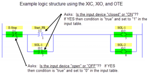
Synopsis of the example logic:
Whenever the momentary Start_PB is pressed, the I:1/1 input bit is scanned as “true” and passes logical continuity to outputs O:2/5 and O:2/6. These outputs become “true”, and power is supplied via the output module to the solenoids connected to these terminal points. Also; O:2/5 acts in a holding circuit capacity by the assignment of an internal memory bit to the branched XIC, so that these solenoids remain “true” until the E-Stop is used to end the process.