PLC Programming Using RS Logix 500: Advanced Concepts of Ladder Logic Programming
The book series “PLC Programming Using RS Logix 500”, provides a guided, step-by-step approach to learning how to write ladder logic programs. Ladder programs are one of the principle types of control programming used in today’s manufacturing and industrial environments.
Advanced Concepts of Ladder Logic Programming is the second book of this series, and teaches some of the more advanced programming techniques for the SLC-500 and MicroLogix family of processors. These processors are still widely used, and I believe they provide a perfect vehicle for learning to program. These are among the many topics detailed in Advanced Concepts.
- Understanding Communication and Protocols
- Specialized Action Instructions
- Building Nested Timer & Counter Logic
- Using Retentive Timers
- Using Math and Scaling Instructions
- Using the Status File
- Analog Modules and the PID Instruction
- Using the Register & Comparison Instructions
- How to program for Program-flow
- Using Fault Routines and Clearing Processor faults
This second book; together with the companion books in this series, has been written to help you achieve proficiency and mastery in the field of automation control programming. The topics and methods presented here will provide a valuable resource for those of you interested in programming your own automation control projects.
Here is a brief excerpt from the book on the subject of Comparison instructions:
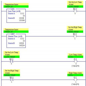
In the previous program example you noticed several examples of “comparison” instructions. These “question–asking” conditions are “true” when their conditions are met, and pass logical continuity down to whatever “action-performing” output is at the end of the rung.
In these example rungs, you see the GEQ “greater than or equal to”, and the LES “less than” instructions. Other comparison instructions that are part of the SLC-500 instruction set are the GRT “greater than”, the LEQ “less than or equal to”, the EQU “equal to”, NEQ “not equal”, the MEQ “masked equal”, and the LIM “limit test” instruction.

Comparison instructions can be used in a variety of interesting ways. In this example, I used them to qualify and set a bit for certain alarms, and to establish fan speeds at predetermined levels of temperature. However; they can also be used to qualify operator selections, such as with a three position switch or BCD input selections, and can control the program flow to specific sections of ladder logic or subroutines.
As you can see, these can be used to compare integer values, constants, or a single bit. The basic parameter constructs for the GRT, GEQ, LES, LEQ, EQU, and NEQ, are that the “source A” parameter must be an integer address, while “source B” can be either an address or a constant.
Here is a brief example of using another type of comparison instruction, the Limit or (LIM) instruction.

The LIM, or “limit test” does exactly as the term implies. If the test value is within the range of a high and low limit, the instruction becomes “true”. If the “test parameter” is entered as an address, then the high limit and low limit can be either an address, such as N7:11, or simply a constant. If the “test parameter” is entered as a constant, then the high and low limits must be entered as addresses. Here is the basic logic rung showing how this instruction might have been used in the programming example from the last chapter.
Where N7:10, a scaled value for temperature input, is used to send the speed signal to the VFD driven circulation fan. If scaled temperature is between the low and high limits of the proportional range, the instruction is “true” and the “high fan spd” bit is turned on.

